
|
|
|
|
Adjusting the steering stem bearings on a Gold Wing is a tricky proposition. First, it is hard to get things dismantled enough to access the steering stem and then you need two specialized tools to "git 'er done". Also note, this is for an '86 Interstate model - other years or models may differ from what I have presented. I hate removing anything if I don't have to and will look for shortcuts whenever I can. While I occasionally find I must do it "the right way", quite often the shortcut way works fine. Also, if you try this, you are on your own. I make no guarantees or promises. This information is offered in good faith and worked well for me. Having said that:
First, remove the plastic cover over the center of the handlebars and the metal wire & hose shield. Now remove the left handlebar clamp and look for a small punchmark on the handlebars at the left edge of the clamp saddle. This is the reference mark for the handlebar position, so when you replace the handlebars you can get them back in the same spot. Place a heavy cloth or a cloth and then a scrap of cardboard on the top front of the false tank. Now remove the right clamp and lift off the handlebars and place them down on the cloth / cardboard you laid on the false tank.
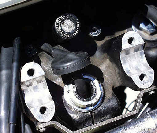
There is a wire bundle that runs down through the center of the steering stem. This is for the turn signal self-canceling switch. That is one item we HAVE to remove and it is bit of a bugger. First, pull out as much of this wire bundle where it runs down into the fairing area as you can. Pull the rubber cap off the steering stem and start sliding it back along the wire bundle sheathing, a little silicone spray can help lubricate things here. You need to get enough wire slack here so when you remove the signal switch out the bottom of the stem, you can reach the plug-in for it. Look underneath the stem area up inside the forward fairing section. There is a black plate that covers the area below the steering stem. There are 2 small phillips head screws visible on the face of the plate. Remove them. Unfortunately there are 2 more screws at the front of the plate that are not accessible without removing the fairing (at least I couldn't see how to do it). I simply grabbed the rear edge of the plate and pulled down and forward, bending it at the forward edge. Yes, it is a brutish method, but it easily bends back and the screw holes lined up.
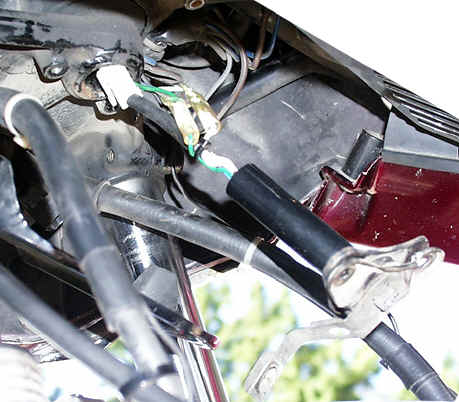
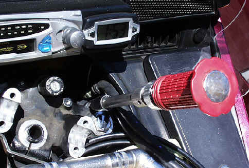
Now you can remove the self-canceling switch which has 3 fasteners holding it in place. Drop it down until you can access the plug-in connectors. You may have to go back topside and get more slack in the wire. Work slowly and gently as the wires are small, and while it didn't happen to me, I could see where you could break some wires if you became impatient and heavy-handed. Once you have it all unplugged, pull the wire bundle back out the top of the stem. Now you can remove the top nut on the stem. This is NOT the adjusting nut, but holds the triple clamp to the stem. It is fairly tight and this is where you need your first special tool.
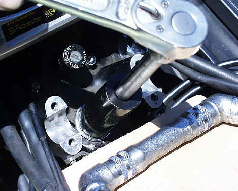
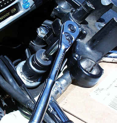
Use that tool to remove the top nut and washer. Now the top triple-clamp must come off. There are 2 phillips-head screws next to each fork tube. They are fairly tight and I found the best way to remove then without stripping the heads was to use an impact driver with a 6" socket extension and phillips bit in the end. I was able to loosen the screws just by using it as a big screwdriver instead of beating on it.
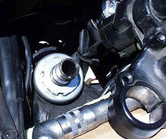
Now loosen the 3 Allen-head socket screws on the sides of the triple clamp (one at each fork tube and one at the steering stem) and slide it up off the forks and steering stem. You'll now see another large nut, but this is just the locknut with a tanged washer under it. Bend the 2 tangs out flat and the nut should spin off by hand. Remove the tanged lockwasher and you will finally see the steering stem adjusting nut.
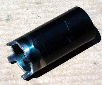
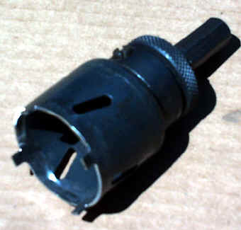
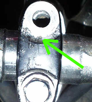
Unfortunately, this requires a different size socket from the top nut. I made mine from an old 1 3/4" holesaw.
The inside diameter was perfect and only required careful grinding to create the tangs.
Now comes the tricky part. How tight do you get this thing??? Apparently, the factory manual specifies 4 lbs. of pull measured at the fork, however, this is with NO OTHER RESISTANCE. In other words, no hoses or wires or cables or ANYTHING that would interfere with the fork movement. This would mean completely tearing down the front end of the bike. I have a Haynes manual which simply specifies 174 - 217 in. lbs. (notice INCH pounds), I went with the high end of that and I think it turned out just fine. To put it all back together, the tanged lockwasher goes back on, then the lock nut, FINGER TIGHT ONLY until the tangs can be bent back up to the flats of the locknut. Next the triple clamp slides back on. Tighten the phillips head screws next to the fork tubes, THEN the 3 socket head screws on the triple clamp. Now the top washer and nut. The top nut gets tightened to 72 ft. lbs. Feed the signal cancel wiring back down and connect the wires - watch the color code on the 2 individual wires. Push the signal cancel switch back up, bolt it back into place and pull the excess wire back up and slide the rubber cap back down the wire harness and onto the top of the steering stem. Replace the handlebars noting the position of the punch mark so you get them back in the same position - or reposition them if you would like to try a more forward or rearward position. Tighten the handlebar clamps to 20 ft. lbs. and replace the metal wire & hose shield and the plastic cover. Note that there is a punch mark on top of each fork clamp which indicates "forward" position of the clamp and also that the forward bolt should be tightened first and then the rear bolt. Thanks to Hawker22 for pointing this out.
Now take 'er out for a ride and see how much more solid and stable it feels. It should also easily return to center position. If you have to consciously push the handlebars back to center, then the bearings are too tight. Fortunately, with the tools and the experience of the first time a second "go-round" isn't so much of a job. Keep on Wingin' !
|